*Update*
Be sure to check out the other posts in this series below.
Part 1
Part 2
Now we are starting to make some headway into making this stock ShapeOko kit into something resembling a CNC Pick and Place Machine. I am quite pleased with the progress so far, and I am learning a lot along the way. For instance, I have discovered that blunt tip dispensing needles with luer lock connections are non-concentric, but more on that later. For now, let's talk about some of the parts that are making this PnP take shape; specifically the head unit and the PnP fixture.


Below, you can see the pneumatic cylinder installed. Note the hole position, and don't forget to install the GT2 belt prior to continuing, otherwise you are likely to gain the authors experience in re-assembly.

In the next photo you can see the stepper motor installed with the stepper motor mount from Servo City.
Install the diameter 5 mm I.D. GT2 pulley on the stepper motor shaft.

Prepare the aluminum plate and brackets as shown.

And install the solder paste syringe holder using wood screws. For this, I countersunk the aluminum plate so that the wood screw heads were below the surface.

Attach the solder paste syringe holder assembly to the front of the aluminum channel using 6-32 x 1/4" BHCS's as shown. It is important to do this now, as it could affect the vertical clearance on the vacuum shaft. The author was able to install qty 3, 6-32 screws during this operation before discovering the stepper motor was blocking one of the screw holes. It was decided to move on with life instead of trying to increase the number of fasteners further.

Ok, the steps shown below are the most complicated, but I think you will manage to follow along just fine. Temporarily install the vacuum shaft and top bearing mount. You may elect to install this with one screw. Slide the shaft axially to detect end float. Measure, if you can, this displacement. Mine was 0.015". Otherwise, you can attempt an iterative process of fitment.
Remove the top bearing plate, install the dia 8 mm I.D. GT2 pulley, and install one of the shims from the arbor shim kit. Since I knew my end float was 0.015", I selected a 0.012" shim. This would leave me with 0.003" clearance.
Bolt the top bearing mount in place, and check that the shaft rotates freely and there is minimal, but perceptible end float. Mine was predictably measured to be 0.003" axial clearance after assembly. If you cannot rotate the shaft, or cannot detect/measure end float, you should select a smaller shim and repeat.
Below you can see the luer lock adapter and blunt dispensing needle installed ( line item #1 ).

Here is the assembled head unit interfaced to the ShapeOko gantry via an 80/20 extrusion angle bracket.

Remember that spool valve I mentioned earlier? here it is installed to the head unit with a Servo City P/N: 545424


Be sure to check out the other posts in this series below.
Part 1
Part 2
Now we are starting to make some headway into making this stock ShapeOko kit into something resembling a CNC Pick and Place Machine. I am quite pleased with the progress so far, and I am learning a lot along the way. For instance, I have discovered that blunt tip dispensing needles with luer lock connections are non-concentric, but more on that later. For now, let's talk about some of the parts that are making this PnP take shape; specifically the head unit and the PnP fixture.
Head Unit:
The purpose of the head unit on this PnP machine is to facilitate the following operations:
- Advance the component tape to present a new component for placement.
- Vacuum grip to pick up a component for placement.
- Rotate the picked up component to the correct orientation for placement on the PCB.
- Hold a syringe of solder paste for robotic solder paste dispensing.
When designing the head unit I wanted it to be made from primarily off the shelf parts. This speeds up development and allows a distributed approach for duplication should any reader wish to replicate the same. I was able to achieve this ideal save one part, which I turned on a lathe. The rest of the parts for the head unit came from online retailers that are listed below.
Here are a few pictures of the head unit assembled.
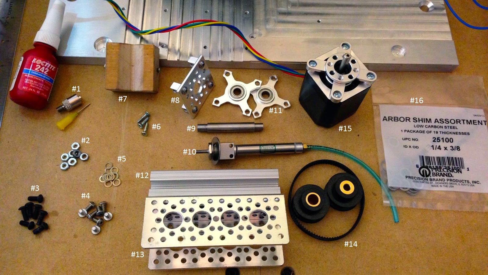
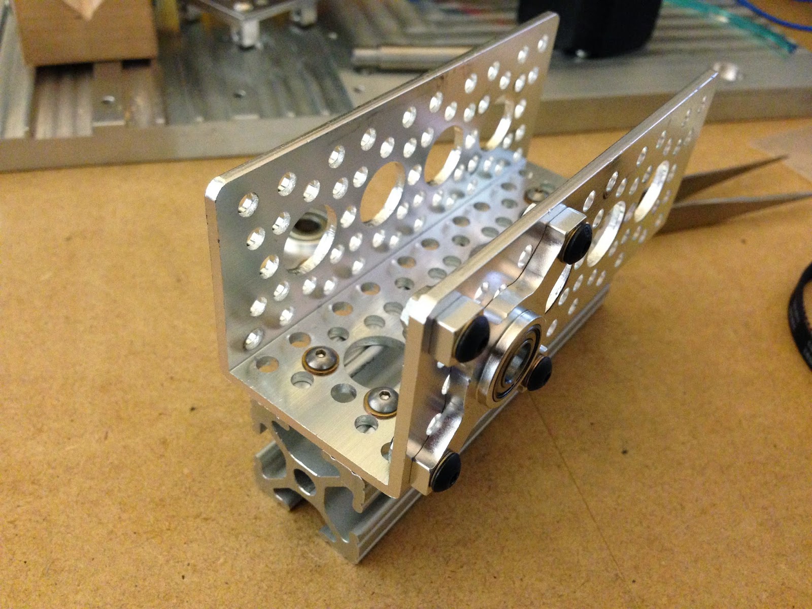
Below is a photo of the head unit prior to assembly. It is annotated with numbers which will correspond to a descriptive list.
Refer to the image above and the list below for part numbers &c. I see now that I left off an annotation number for the bottle of loctite. It is slightly optional, but probably a good idea for many of the fasteners as stepper motors can be a bit vibratey. All of the parts ( except #9 ) came from the following vendors: McMaster-Carr, Servo City, SDP/SI, Clippard, and eBay.
- A 10-32 threaded female luer lock adapter and blunt tip dispensing needle from McMaster Carr. Respective P/N's: 51465k151 and 75165A682 and 75165A677
- 6-32 nuts. I had these. They measure 0.245" across the flats.
- 6-32 x 3/8" Long, Button Head Cap Screws. I purchased these from a local hardware store.
- 6-32 x 1/4" Long, Button Head Cap Screws. McMaster P/N: 98164a106
- #6 Washers. McMaster P/N: 98032a436
- Wood Screws to hold the maple block ( #7 ) to the head.
- This is a v-cut block of wood for holding the solder paste syringe.
- A flat channel bracket from Servo City P/N: 585468 and a pair of Servo City 90 deg. dual mounts P/N: 585470. All of this is held together with screws ( line item #4 ) and washers ( line item #5 ).
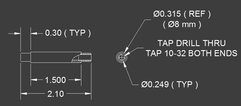
- I turned this shaft out of some 8 mm bar stock ordered from McMaster-Carr P/N: 1272t38 A drawing to make this part is below.
- A Clippard pneumatic cylinder, plus a hardware store washer. This is for drag feeding the SMD tape. Clippard P/N: FSR-05-1 1/2
- Two 1/4" I.D. bearing mounts from Servo City P/N: 535110
- 1" x 1" 80/20 Extrusion. I cut mine slightly shorter ( < 3.75" ) than the Servo city bracket this is mounted to.
- 3.75" Aluminum channel from Servo City P/N: 585443
- GT2 Timing belt and 2 disparate pulleys from SDP-SI P/N: A6R51M093060, A6Z51M036DF0608, and A6Z51M036DF0605
- A NEMA 17 stepper from eBay, plus a stepper motor mount from Servo City P/N: 555152
- An arbor shim kit for setting the end play of the diameter 8 mm shaft ( line item #9 ). McMaster P/N: 3088a928
In the assembled head unit photos you can also see a brass spool valve for diverting the CO2 flow betwixt the solder paste syringe or pneumatic cylinder. I probably should have just ordered another solenoid, but the diverter valve is Clippard P/N: HTV-3F.
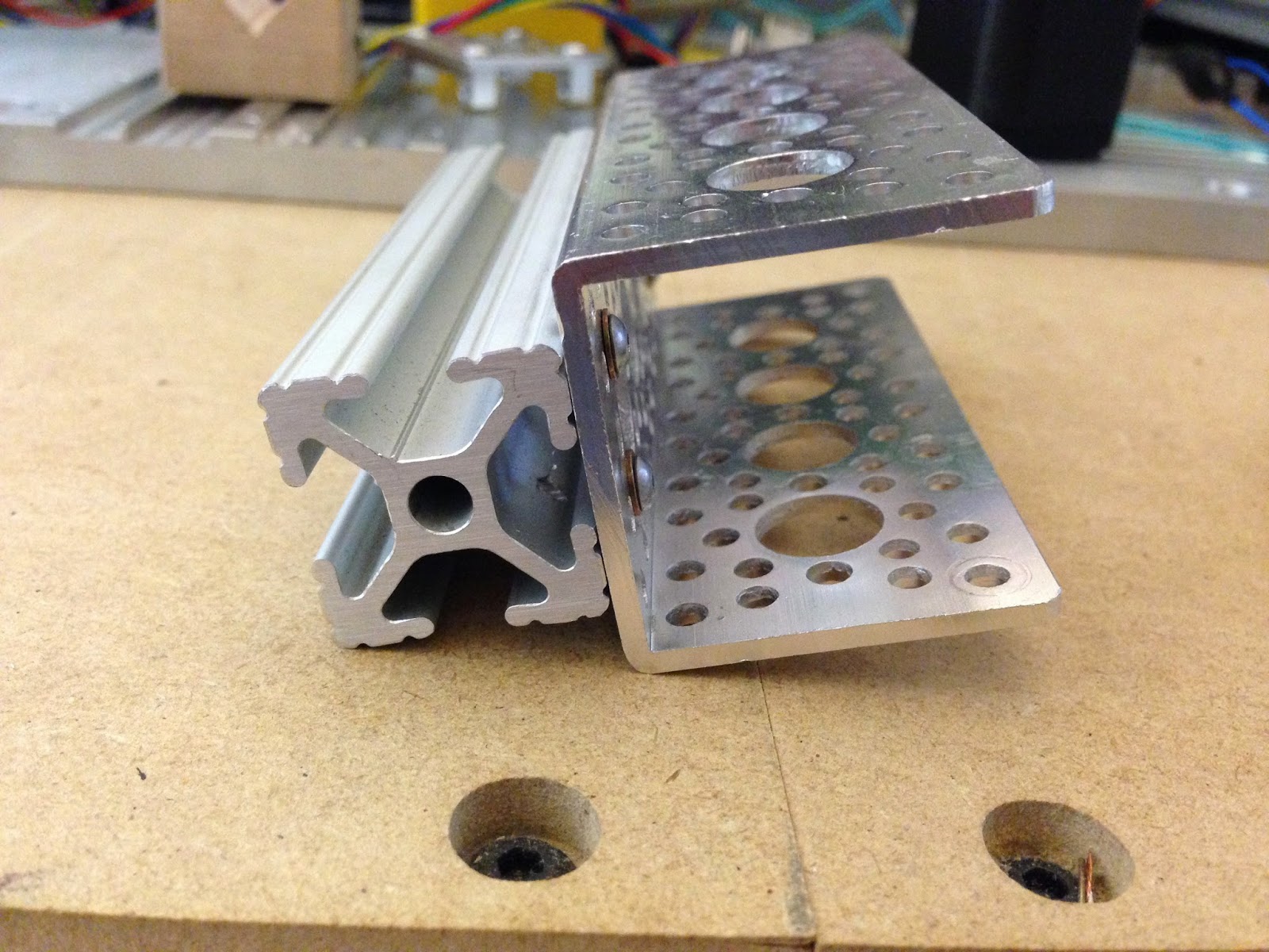
Lets begin assembling the head unit by attaching the aluminum channel from Servo City ( line item #13 ) to the 80/20 extrusion ( line item #13 ). You will notice I used non-standard mounting methods here. I drilled and tapped the 80/20 extrusion for 40-40 BHCS ( Button Head Cap Screws ). This was necessary because the standard 1/4-20 BHCS plus t-slot nuts came too close to my pulleys and belt for my liking. One way around this would be to select a smaller tooth number pulleys and belt, while maintaining the same center to center distance.
Next up, attach the bottom bearing mount using some 6-32 x 3/8" BHCS's, washers and nuts as shown below.
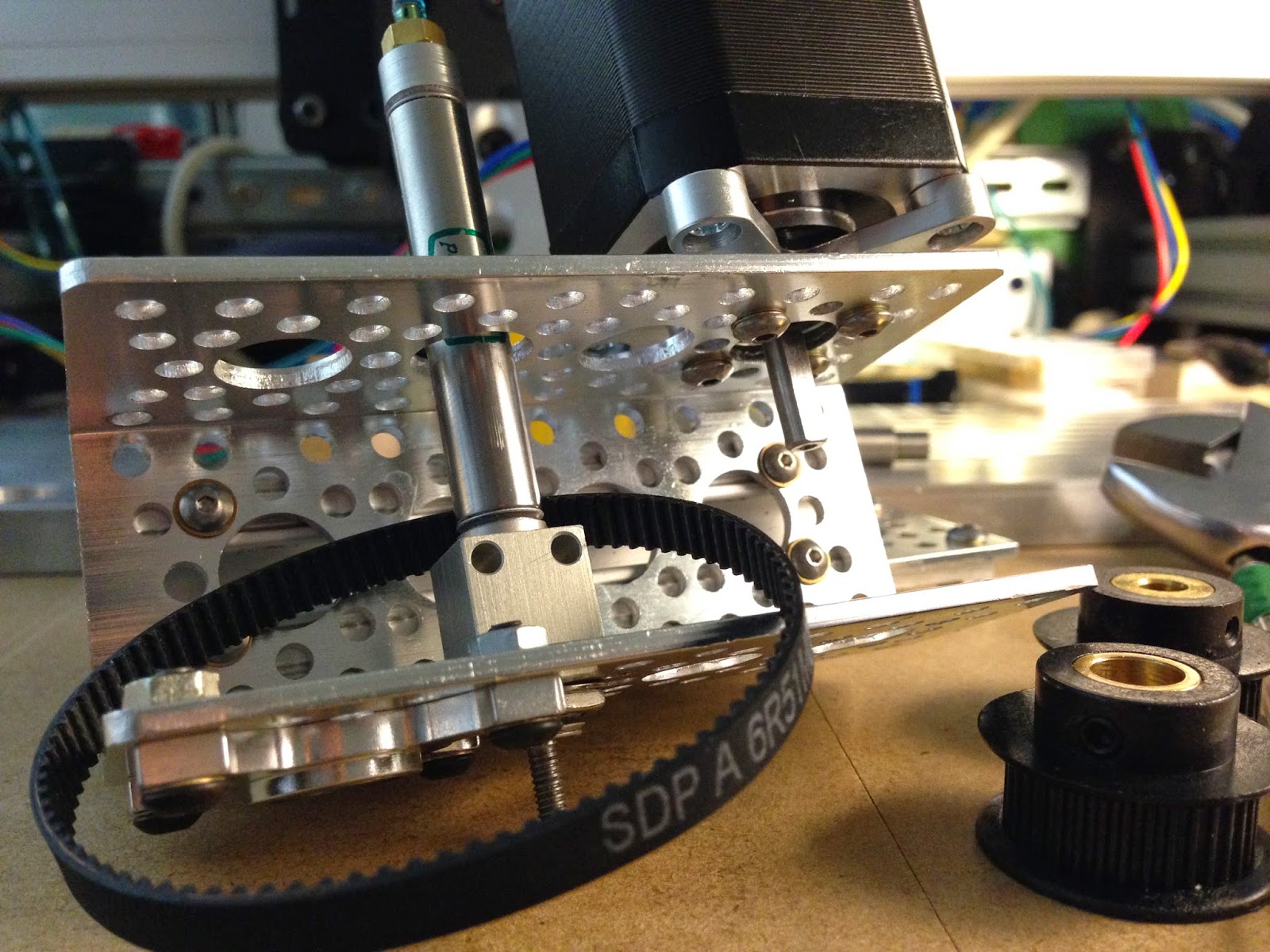
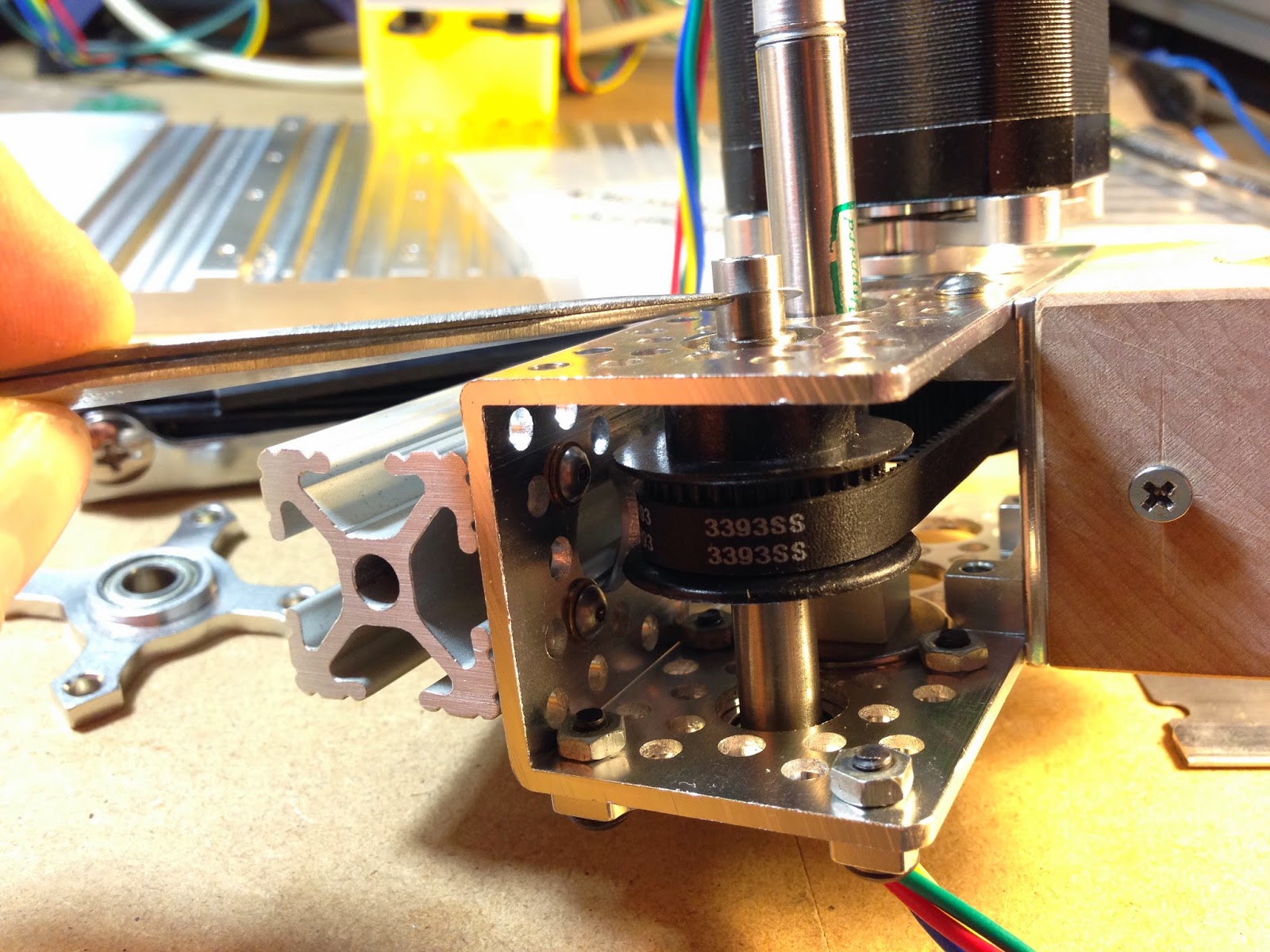
Below, you can see the pneumatic cylinder installed. Note the hole position, and don't forget to install the GT2 belt prior to continuing, otherwise you are likely to gain the authors experience in re-assembly.
In the next photo you can see the stepper motor installed with the stepper motor mount from Servo City.
Install the diameter 5 mm I.D. GT2 pulley on the stepper motor shaft.
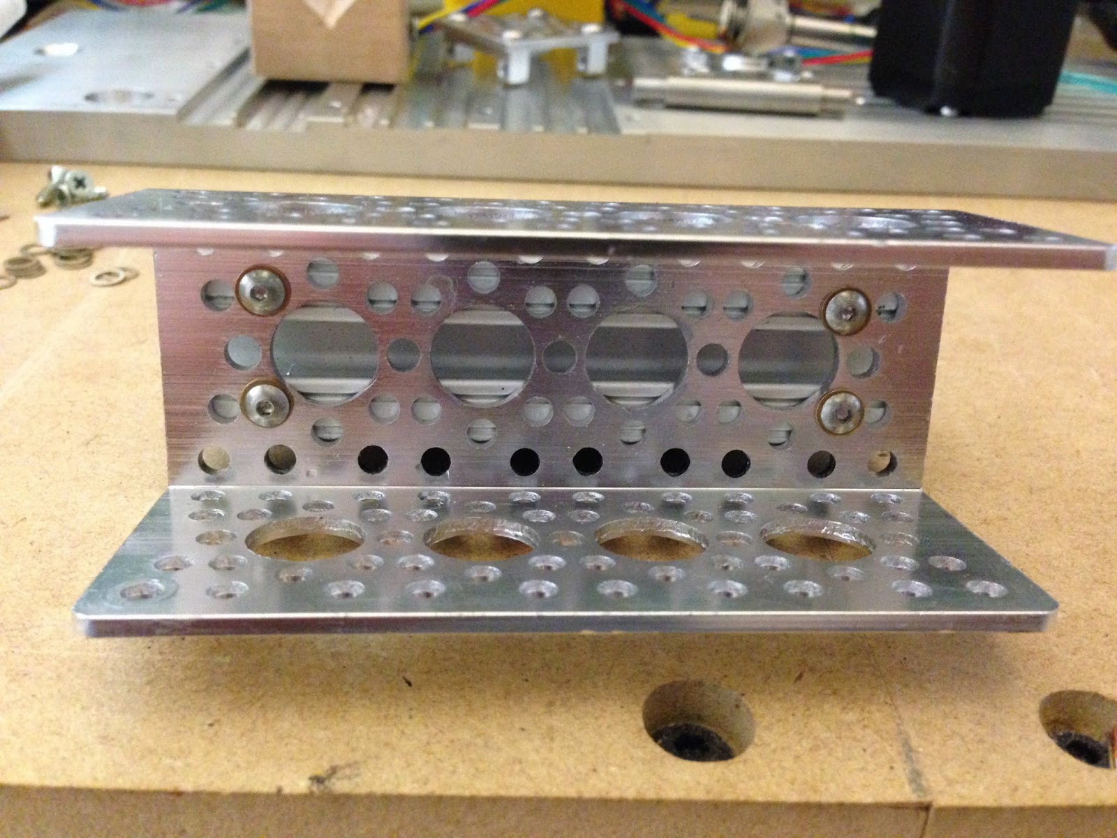
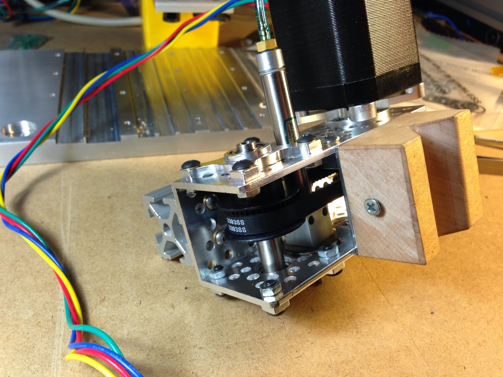
Prepare the aluminum plate and brackets as shown.
And install the solder paste syringe holder using wood screws. For this, I countersunk the aluminum plate so that the wood screw heads were below the surface.
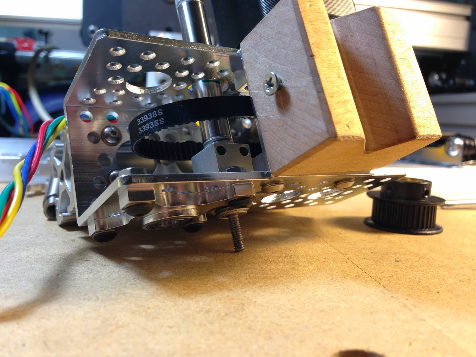
Attach the solder paste syringe holder assembly to the front of the aluminum channel using 6-32 x 1/4" BHCS's as shown. It is important to do this now, as it could affect the vertical clearance on the vacuum shaft. The author was able to install qty 3, 6-32 screws during this operation before discovering the stepper motor was blocking one of the screw holes. It was decided to move on with life instead of trying to increase the number of fasteners further.
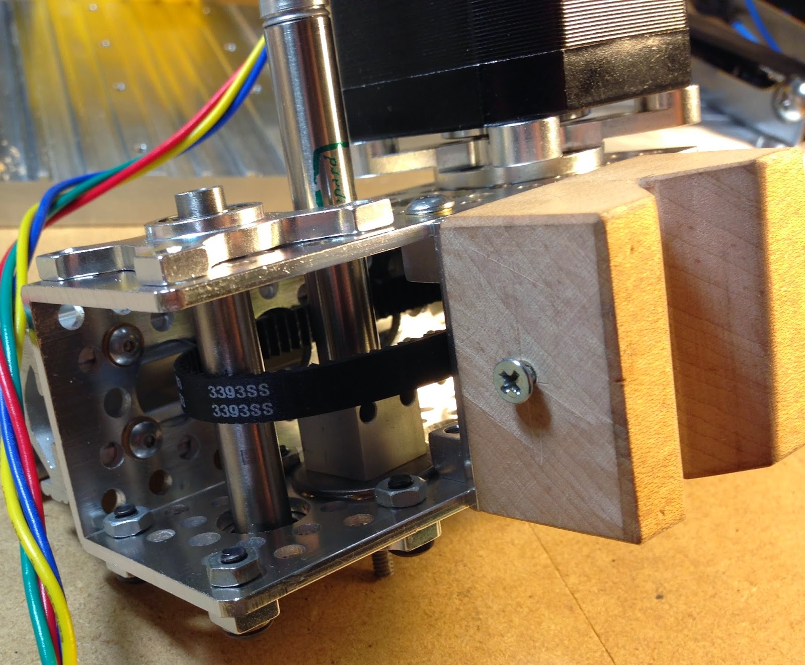
Ok, the steps shown below are the most complicated, but I think you will manage to follow along just fine. Temporarily install the vacuum shaft and top bearing mount. You may elect to install this with one screw. Slide the shaft axially to detect end float. Measure, if you can, this displacement. Mine was 0.015". Otherwise, you can attempt an iterative process of fitment.
Remove the top bearing plate, install the dia 8 mm I.D. GT2 pulley, and install one of the shims from the arbor shim kit. Since I knew my end float was 0.015", I selected a 0.012" shim. This would leave me with 0.003" clearance.
Bolt the top bearing mount in place, and check that the shaft rotates freely and there is minimal, but perceptible end float. Mine was predictably measured to be 0.003" axial clearance after assembly. If you cannot rotate the shaft, or cannot detect/measure end float, you should select a smaller shim and repeat.
Below you can see the luer lock adapter and blunt dispensing needle installed ( line item #1 ).
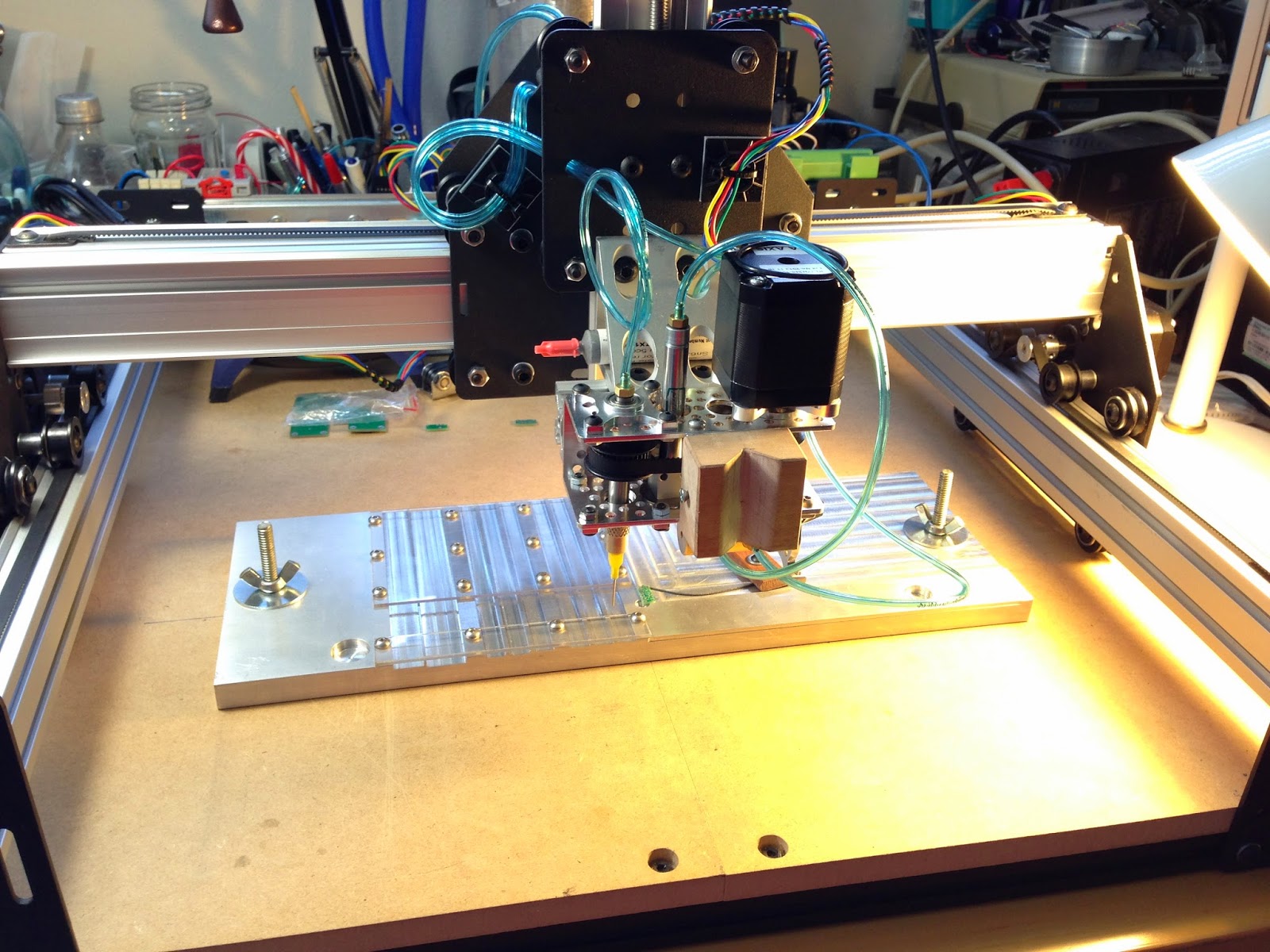
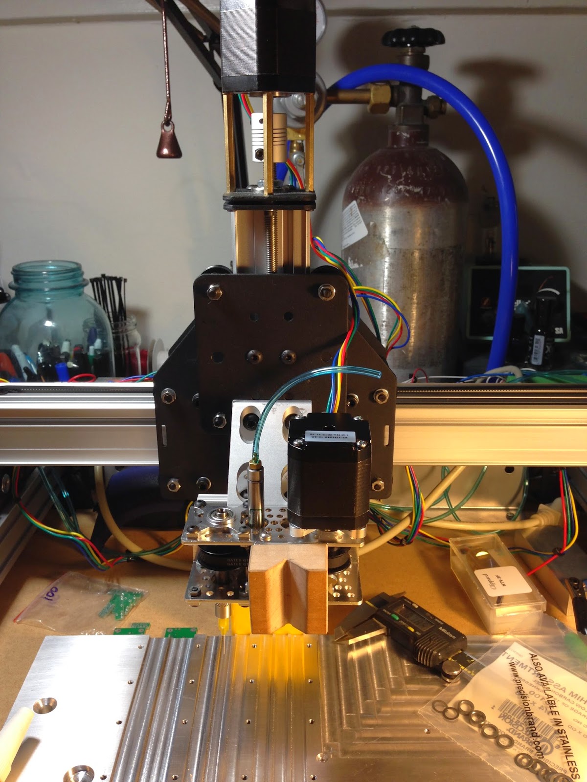
Here is the assembled head unit interfaced to the ShapeOko gantry via an 80/20 extrusion angle bracket.
Remember that spool valve I mentioned earlier? here it is installed to the head unit with a Servo City P/N: 545424
This is where I discovered just how bent/curved/or otherwise not straight the vacuum needle was. When I rotated the head unit with the stepper motor, the needle spun around and orbited too. So, I bent the needle a little and was able to get it pretty concentric. Then I removed the needle, and re-installed on the second start thread only to discover the needle was non-concentric again. For now, I will continue with this setup, but it may be worth investigating some precision needles at some point - probably making them.
If you recall the shaft that needs to be fabricated, below you can find a drawing. Basically the length of the diameter 8 mm shoulder is going to be determined by your particular setup. As it is drawn below worked well for me, but you may do well to have a measure of your system first.
The PnP Fixture:
You have probably seen the aluminum plate with milled slots, clocking holes, a shoulder register and a bunch of tapped holes. This is my vision for making a low volume, home pick and place machine. I can make as many different plates as I need based on the circuit board I want to fabricate.
The design is made pretty universal. There are 4 tracks for resistors or transistors, two tracks for capacitors, one for a regulator and one for a mosfet. I selected these parts and subsequently the track dimensions based on the boards I wanted to populate first. If I have a new board design in the future, and this setup does not have tracks for the correct parts, I can make a new fixture.
Here is how I envision this fixture working. I say envision, because I am still learning how to write G-Code, and I am not sure how to do what I want just yet. At the time of this writing, I am currently working on the programming I am about to describe.
If you look at the fixture you will see two countersunk holes for flat head screws. This fixture will be bolted to the ShapeOko MDF work surface here.
Inboard and towards the front, you will see two round bores of different diameters. They would have been the same size, but I messed one up while machining. Since the fixture is unlikely to ever be bolted down, perfectly aligned with the machine coordinates, I am trying to do the following. Probe each of these two holes, calculate the angle between the machine coordinate system and the line made by joining these two center points, and rotating a new set of coordinates for the machine to use that are aligned with this fixture.
There is an X-Y register for locating the circuit board. This X-Y ( 0,0 ) is located 5.000" right and 0.500" toward the rear from the bottom left probe bore. Using this new origin I know where my circuit board pads are ( from the gerber files ), and I also know where to tell the machine to look for each type of component to place.
To hold the circuit board in this register, orienting it's X-Y ( 0,0 ) I used a piece of an old coping saw blade. Held in place on one end by a Jarrah wood clamp, the other end applies enough spring pressure to keep the board steady and registered during assembly.
Things are starting to look like this might just work. I still have a long way to go with G-Code and tuning the machine operations. I haven't even fed any parts yet! Never the less, I keep chipping away at the subcomponents on this job.
Incidentally, I will probably be showing this machine off at the Ann Arbor Mini Maker Faire, so if you are in the area, be sure to stop by.
Comments